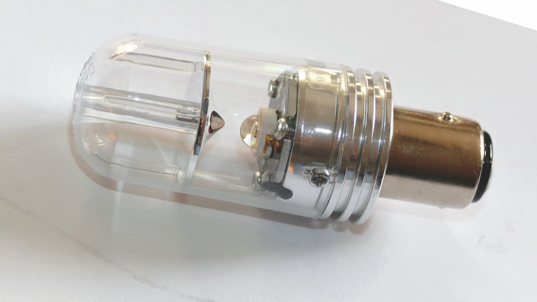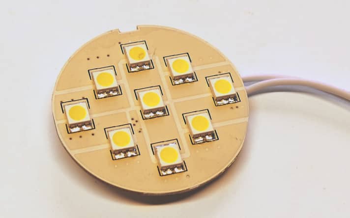
A report from the US Coast Guard recently caused a stir: the authority had established that reception in VHF marine radio becomes very poor or even impossible if certain lights with LED technology are operated in the vicinity. A list of affected makes is not yet available. Instead, the Coast Guard is calling on all water sports enthusiasts to report such incidents so that more detailed investigations can be carried out.
Do we really have to switch back to light bulbs now? Certainly not, because as is so often the case, it is a few black sheep that threaten to discredit an entire appliance category. What's more, you can easily check whether your boat is affected by the problem using on-board tools, as described below.

Background: The actual LED (light-emitting diode) component does not cause any interference. However, the individual LED cannot be operated directly on the 12-volt vehicle electrical system. Each LED light therefore contains a circuit for adaptation. The electronic components required for this are located together with the LEDs on a circuit board. The whole thing is known as a light source.
There are basically two options for adjustment, linear or with a switching regulator. The linear variant is completely unproblematic in terms of radio, but is not very efficient and can only be realised for weak luminaires. Switching regulators are therefore the standard for LED light sources today. And it is precisely these that can cause problems if the design is unfavourable.
A defined current is supplied to the LED component to ensure stable operation. With white lights, a voltage of around 3 volts is then set depending on the brightness and temperature. The voltage in a vehicle electrical system with lead
batteries is between 11 and 13 volts, depending on the state of charge, and up to 15 volts are possible when charging. This is therefore completely incongruous; the electronics have to compensate for the difference.
In the linear method, the manufacturer usually connects three LEDs and a resistor in series. The latter literally burns up the difference between the LED and the on-board voltage. Although the current depends on the level of the on-board voltage, it always flows evenly. In principle, interference cannot occur in this way.
The way a switching regulator works is completely different: a transistor switches on and off very quickly, and a coil connected behind it can practically transform the voltage from the vehicle electrical system down to the value required at the LED. The advantage here: In contrast to the resistor, there are only minimal losses, and the light can also be used over a very wide voltage range (12 to 24 volts are common).
To keep components and therefore the light source as small as possible, the transistor must operate at a high frequency. In turn, fast switching is necessary for good efficiency, as most losses occur in the transition area between "on" and "off". Unfortunately, both of these factors together also result in the
recipe for an interference transmitter:
The electronics generate so-called harmonics, which are multiples of the original operating frequency. The connection cables then spread this signal throughout the ship.
This can be prevented with a few cheap but skilfully used components. However, minimising production and development costs is probably tempting some manufacturers to forego these measures.
Such problems are usually first noticed in radiotelephony or radio. However, everything that has to do with radio is affected, including AIS, DSC, Navtex and weather receivers.
In the case of lights labelled with the familiar CE mark, the manufacturer guarantees that they comply with the standards. They should not actually cause any perceptible interference.
To illustrate the effects in on-board operation, we looked for examples of potential interference emissions on two boats fully equipped with LED technology and in the laboratory. As high-frequency measurement chambers that can accommodate an entire boat are rare, a simpler method had to be used for verification: Comparing the radio spectrum of interest once with and once without the suspect device being switched on.
We use a so-called panorama receiver for this purpose. This is practically a radio that records a very wide frequency range and graphically displays the intensity of the signals received. We focussed on the ranges that are important for ship operation: Weather transmissions from the DWD at 147 kilohertz, Navtex at 500 kilohertz, radio from 88 to 108 megahertz and VHF marine radio with AIS and DSC from 156 to 162 megahertz.

During the tests on board, no interference related to LED lights was initially observed in any of the frequency ranges mentioned. There were only conspicuous features during the subsequent examination of 20 lights from the editorial pool in the laboratory; one of them generated detectable signals in the long and medium wave range. However, these were not emitted into the room, we were only able to detect them on the connecting cables.
The diagram clearly shows that the interference caused by the light at low frequencies only occurs in small ranges, in between there is silence, so to speak. In addition, the disturbed frequencies change with the operating voltage. It is quite possible that the reception of a certain transmitter is only disturbed when, for example, the charger is in operation.
However, the source of interference is not the charger itself: The LED only hits the frequency at this voltage.
The higher the frequency, the wider the interfered sections. In the VHF range (radio and marine radio), the individual peaks merged into a uniform noise.
This light could indeed have caused problems - if its supply cables had been mounted directly next to the receiving antenna. At a distance of just one metre from the measuring antenna, nothing more could be heard.
In almost all known incidents to date, the causes were retrofit LED inserts in the top or tricolour light. This fits in with our findings, as only this light would be close enough to the antenna. Incidentally, approved LED position lights that were tested did not have this problem.
Here's how you can do a test on your own boat: First switch off all suspects, in this case LED or energy-saving lights and any inverters, and disconnect your boat from the shore power supply. Find a VHF channel with little traffic. Then turn the squelch all the way up and adjust the volume so that the noise can still be heard clearly.
Now switch on each light in turn and listen for a clear change in the noise. A crackling sound at the moment of switching is not critical, only what lasts for more than a second counts. If in doubt, switch the light on again and repeat the test on a different VHF channel.
For Navtex and weather reception, the test is somewhat more complex. Firstly, call up the display of the current incoming signal on the receiver and wait for a clearly legible incoming message. Now check each time you switch on the light to see if there are any errors in the text. The probability that you will find something here is particularly high with older 12-volt fluorescent lamps.
While you're at it: Extend your investigation to inverters and the chargers of notebooks and mobile phones - there are black sheep everywhere. It is almost impossible to calm down any sources of interference found with on-board equipment. Replace the bulbs with a different brand and check their behaviour within the return period.

