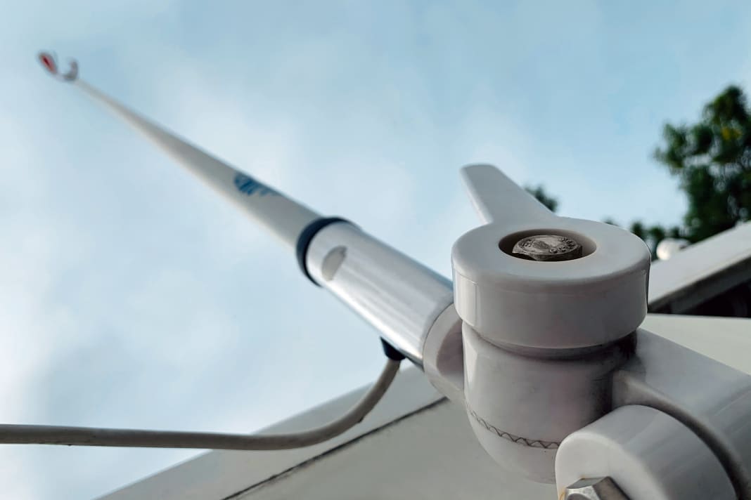


Whether the antenna looks smart and matches the look of the boat can be judged by eye. But what does an antenna really do? We put 14 motor yacht models from four manufacturers to the test in the free-field measurement laboratory of HF-Kompetenz in Handewitt. The prices range from 60 to an impressive 360 euros, and the lengths are between 0.25 and 2.7 metres.
The importers didn't actually want to give us three of them, the most compact ones. We only took them to the test bench to show you the shortcomings of antennas that are too small. But first, a short detour into how they work.
From wire to antenna
Any piece of wire can be an antenna. The only requirement is that the length matches the frequency of the radio signals, which radio operators refer to as resonance. You can try out the effect: Let a rope swing loosely from your hand. At a certain number of strokes, only the ends of the tamp move, the centre remains almost still. You have hit the resonance of the tamp of this length.
VHF marine and ship radio operates at 157 MHz, which is 157 million oscillations per second. You don't have to memorise it, the radio already does this. The wavelength of signals at this frequency is just under two metres. Resonance occurs at half the wavelength and multiples thereof, which is why good VHF antennas are at least one metre long, the so-called dipole.
If you need it smaller, you can wind this dipole onto a GRP rod, which is called a helical dipole. However, its effect quickly diminishes with a shorter rod: the only half-metre antenna in the test only provides a quarter of the signal compared to the full-size version of the same model. Nevertheless, this still results in a perfectly functioning, resonant antenna.
The other method for short antennas: You cut off the lower half of the dipole and place the rest on a sufficiently large metal surface. A quarter of the wavelength of the radiator remains, hence the name: quarter-wave antenna. The three models that the importers prefer not to put on the boat are of this type, none of them delivered usable values. This is due to the system: to get the antenna to resonate, the metal surface would either have to measure exactly the other quarter of the wavelength or be much larger - which never fits on board. As the manufacturer does not know the conditions on the boat, such an antenna cannot be correctly tuned ex works. The table shows the values for the "Banten yacht antenna 0.25m", Glomex RA111 and Scout KM10 are similar.
Profit or loss
Every real antenna works better in certain directions and worse in others. In practice, a vertical dipole emits the transmission energy preferentially in the horizontal plane. The drawing on page 54 shows how you can visualise this from the side. This is good for radio on a boat, as our preferred radio partners are also on the water. Space stations have no marine radio equipment, and contact with submerged submarines is not possible on VHF anyway. From above, however, we want to be heard equally well in all directions, which the vertical dipole actually fulfils perfectly (see above). However, it should be noted that a directional effect can easily occur on the boat, as all metal parts that happen to be resonant on VHF influence the radiation.
The extent to which an antenna concentrates the signal is known as the gain; the effect is the same for both transmission and reception. The radio operator refers to an ideal antenna. This works equally well in all directions, it radiates the signal spherically (isotropically). In fact, such an antenna cannot be built, and in practice it is never needed. It is only a standardised, theoretical reference object.
The ratio of the test specimen to the standard antenna is specified in decibels (dB). This is a logarithmic scale commonly used in radio technology, with which both small and very large ratios result in manageable figures. At 0 dB, the two compared antennas are equally good, 3 dB means twice as good, 6 dB is a factor of four, and 10 dB is a factor of 100.
Results worse than the reference object have negative dB values: half are -3 dB, a quarter -6 dB. The simple dipole is theoretically 2.1 dB better than the omnidirectional reference antenna due to its horizontal orientation. However, it also has a significant effect in the upward and downward directions. Greater focussing in the horizontal direction can be achieved by placing two dipoles at the correct distance from each other, which is how the three long motorboat antennas are constructed. This is theoretically 3 dB better than the dipole in the main direction, which could result in 5.1 dBi, the small i stands for the comparison with the standard antenna.
The antenna cannot generate additional energy, so what is gained in the horizontal plane must be missing in other directions. The diagram above shows how the effect decreases rapidly beyond the horizontal. If such an antenna is not vertical, the range in the tilt direction decreases rapidly.
Amazing results
In the test, we measured the gain of the antennas precisely in the horizontal plane, where the maximum effect would theoretically be expected and where the remote stations are located in practice. The test subjects' gain is far from theoretical. This is mainly due to shifting the main beam direction upwards or downwards. There are many reasons for this, but often the antenna cable is not ideally coupled to the actual radiator. As a result, the cable and the mast become an effective part of the antenna, with an unpredictable influence on the radiation.
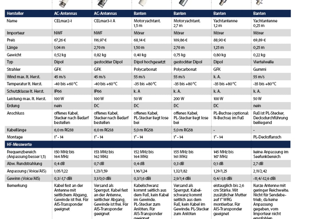


With the simple dipoles, there is a difference of around 2 dB or a factor of 1.5 between the best and worst antenna, but in practice this is hardly noticeable because of the design of the marine radio system: all radio systems of the last 30 years have at least 20 of the 25 watts of permitted transmission power, so they can reach twice the distance to the horizon with all dipoles. And VHF doesn't go any further anyway. If the antenna of the other station disappears under the sky, that's it, the radio waves don't follow the curvature of the earth.
A deviation of the omnidirectional radiation in the horizontal plane from the ideal circle was measurable, but in practice, changes in the signal of less than 1.5 dB are not perceptible with recreational craft radios. Only the extremely short antennas, which are inadequate in any case, were of this magnitude.
The matching provides information on how well the antenna absorbs power from the transmitter. The standing wave ratio (SWR) was measured in the frequency range of the voice channels (Voice) and for AIS (162 MHz). The value should be less than 1.6. It is worth noting that not all antennas are suitable for the operation of AIS transponders due to insufficient adaptation to the AIS frequencies.
Cables and plugs
The correct type of coaxial cable must be used for the radio system. Otherwise, the entire vehicle electrical system acts as an aerial, causing all kinds of side effects and interference - but no proper radio contact. Coaxial cable has two electrical characteristics: The most important is the characteristic impedance, 50 Ohm is always used for radio. This cannot be measured, but results from the geometric relationships between the inner and outer conductors. You can leave the calliper gauge in place: The insulation material also plays a role. Cables without a legible type designation are therefore a case for the scrap metal collection.
The second characteristic value is attenuation, which describes how much energy is lost per metre of cable; incidentally, this is the same for transmission and reception. The rule here is: the thicker, the better. Two types are commonly used in the marine sector: RG58 with an outer diameter of approx. 5 millimetres and RG214 with an outer diameter of 11 millimetres.
The right connection
The inconspicuous cables and plugs are the backbone of every VHF radio system. Important to know: they don't necessarily last forever on board
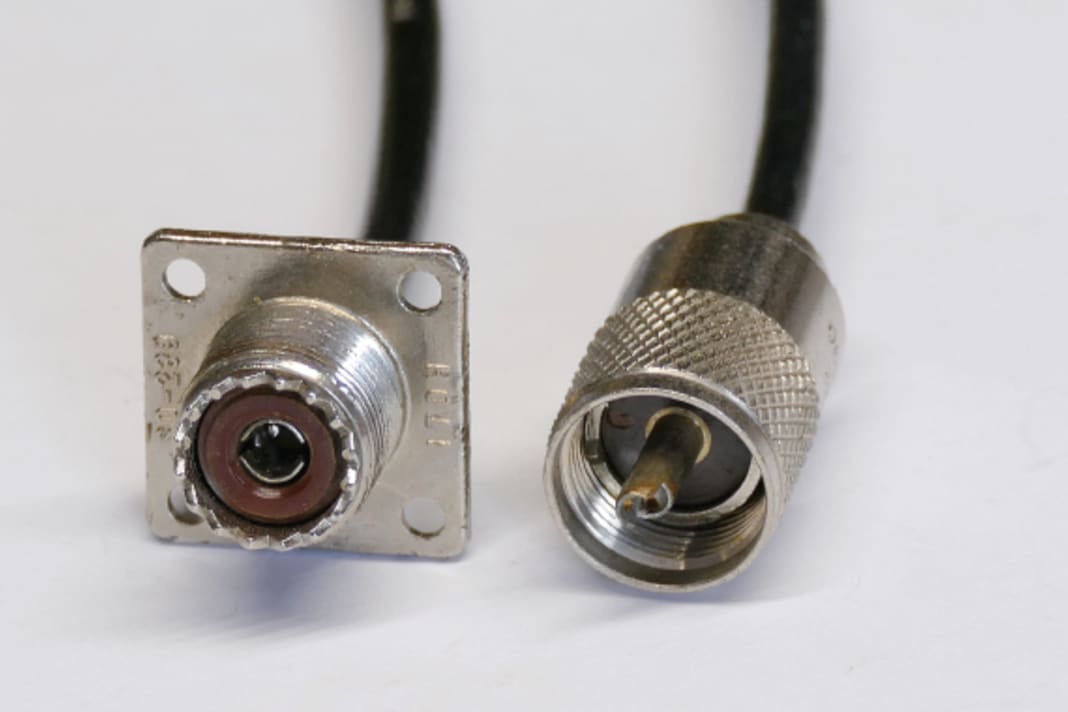
To identify the correct connection types:


On the boat, the mechanical properties of the cable are also important; it must be suitable for use on vehicles and in sea air - even inland. Only cable with tinned or silver-plated, flexible conductors fulfils these requirements, not bare rigid copper. The correct version of the thin version is labelled RG58C/U. The thicker RG214 is only produced in the marine version.
You can usually get by with RG58. This means that an acceptable 20 per cent of the signal is lost over five metres of cable between the radio and the antenna. Expect to pay around 1.50 euros per metre. RG214 is recommended from ten metres upwards. This halves the losses, but quadruples the price.
A plug is required at the end of the antenna cable. You can identify which type must be connected to which end using the pictures above. The designations for the PL system are somewhat confusing: the socket is officially called SO239, the plug PL259. Another name is UHF connector.
Connector installation on coaxial cables is not easy; special tools are required for some types. Errors can seriously impair the function of the radio system and even damage the radio. If you have even the slightest doubt about your own tools, it is better to get a specialised company on board.
Due to vibrations and environmental influences such as UV light, antenna cables of all types are subject to wear. Water that has penetrated through cracks, for example, means that you can still receive, but the transmission signal no longer reaches the aerial. Partial repairs will not help; it is better to replace the entire cable.
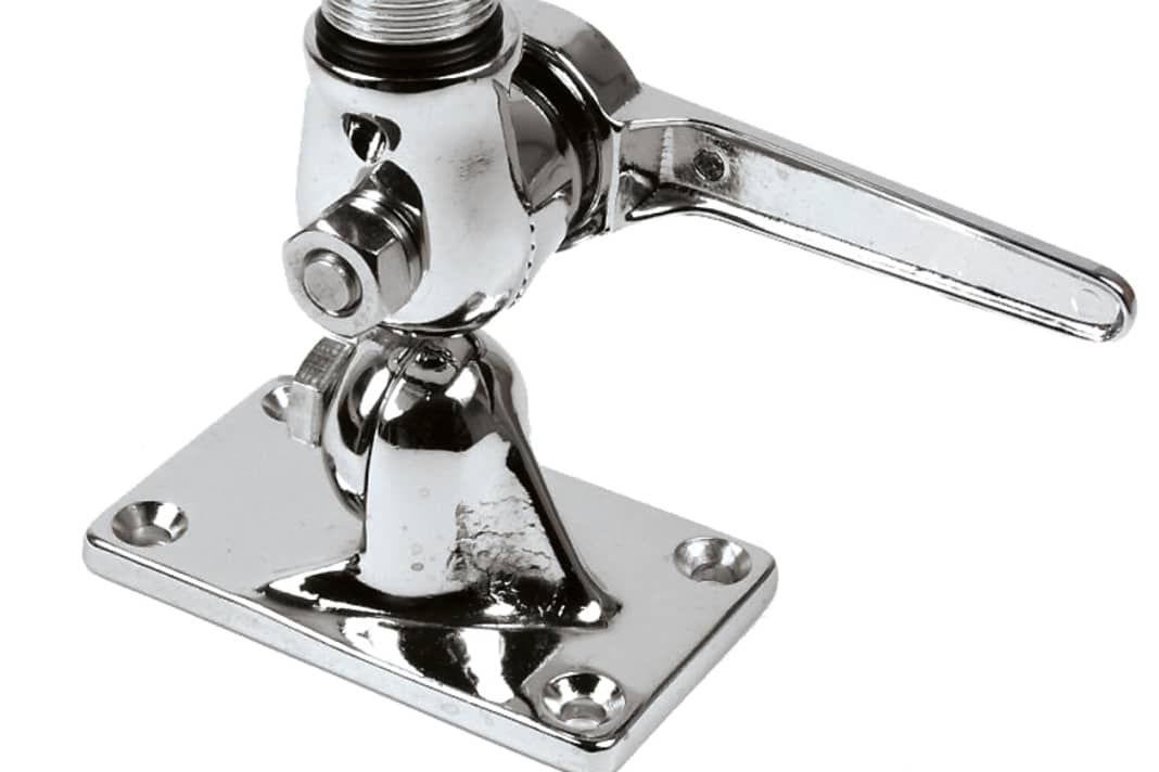
Mounting feet
Stable on deck:


Conclusion
Mounting height is the best way to increase range. Shallow boats in particular benefit from the increased height of the 1.5 metre antennas. Due to their horizontal bundling, the long models with high gain are only suitable for smooth-running yachts with low trim. The half-metre helical dipole is the most compact acceptable antenna.
Also interesting:
- VHF on board: voice radio instead of smartphone
- Workshop: VHF mounting - How to get in touch
