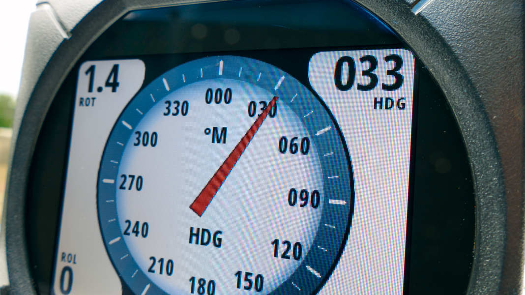
Specific course information is essential for navigation. This applies to the Paper map just like on the screen. At the latest when radar comes on board, there is an acute need for an exact indication of the current orientation of the boat in digital form. Sometimes, however, the choice of hull material makes an electronic compass necessary: On steel ships, the deflection of the conventional magnetic compass is particularly large and correction is time-consuming.
Okay, you're not sailing an iron collection, but a smart plastic yacht. But even on that, there is still enough steel to noticeably irritate a compass. With an electronic compass, the display and sensor are separate, and the latter is relatively easy to install in a place with little distraction. In contrast to its mechanical relative, the electronic compass is relatively easy to get rid of the remaining errors.
In addition to the steering display, the navigation electronics mainly require heading data for the forward-orientated map display, the radar overlay and the autopilot. But why also from the compass - after all, every GPS receiver also displays a course?
Operation
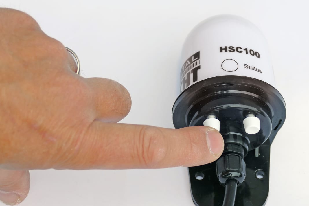
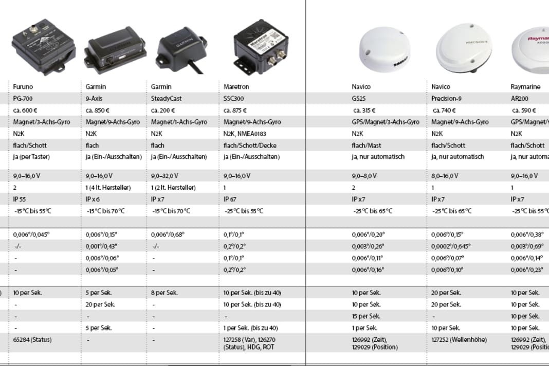
Only two models offer a convenient way to set up the device without the manufacturer's display:


However, this is the direction of movement over the ground, which usually does not correspond to the direction in which the bow is pointing. Anyone travelling on current waters or in tidal areas will be very familiar with this effect. But even on more stationary seas like the Baltic Sea, the water is moving, just not as predictably. Two knots of current offset can easily occur. At a speed of 18 knots, this still results in a difference of up to six degrees between the GPS course and the keel direction. For a radar overlay, this is already a value that makes the image almost unusable, as the chart and echoes no longer match. This is why almost all manufacturers require the heading data from the electronic magnetic compass to activate the overlay display. This is because it doesn't care about speed and current offset, it shows the direction ahead.
The reference from the GPS would be useful for the autopilot, but this data is too slow to steer based on it alone: Your boat must have travelled in the wrong direction for two or three seconds before this is even visible in the GPS data.
Eight devices from six manufacturers were tested. The prices range from 200 to 857 euros. Six models can only be connected via NMEA2000, one only has NMEA0183 and one offers both connections. Two also have an integrated GPS receiver.
The basic function is the same for all eight: a sensor measures the earth's magnetic field to determine where magnetic north is. Unfortunately, this measured value is subject to a high level of noise, which means that the numerical value constantly wobbles back and forth by a few degrees - even if the ship is not moving at all. This can be filtered out, but this makes the compass very slow in its response to course changes. It would no longer be usable for steering and the radar overlay would constantly lag behind the actual conditions. All candidates therefore also work with gyroscopes. These are sensors that detect rotations very quickly and accurately; they are also used in cars for the ESP. In contrast to magnetic field measurement, they provide precise information about course changes in the short term, but cannot maintain direction in the long term - they wander. They don't even know where north is.
Data diversity
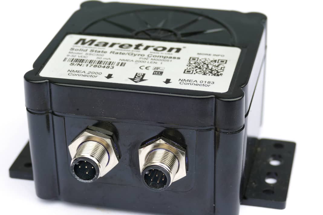
The NMEA2000 interface has standardised connectors, but some manufacturers offer more than would be possible with them:


The magnetic field only serves as a long-term reference; a rotation sensor recognises rapid course changes
However, both complement each other well: in the long term, the course is determined via the magnetic field, while the gyroscope provides information about fast movements. So far, all candidates work in the same way. Major differences arise from the number of axes in which measurements are taken: It is clear that turns around the vertical axis change the course, but what happens if you are travelling at an angle to the wave or if your boat is heavily trimmed while underway? The sensor, which originally only measures in the horizontal plane, is then skewed and also interprets the ups and downs in waves as course deviations. High-quality devices therefore also measure rotations around the longitudinal and transverse axes, which, when calculated accordingly, should theoretically stabilise the display in rough seas.
Gyroscopes can only record movements, not static values. In order to determine a permanent inclination to the side (heel) or in the longitudinal direction (trim), the top models also have sensors for gravity. This results in up to nine axes: magnetic field, rotation and gravity, each in three directions. From this, the compasses essentially generate three values: all provide the heading, which is used by the plotter and radar for north stabilisation, as well as by the autopilot and for the steering display. Here it is important that the value is updated as often as possible. Ten times per second is standard, with Maretron this can be configured to up to 40 updates per second. The fact that Garmin's 9-Axis only provides five updates is compensated for by very up-to-date turn rate data (20 per second). Only Navico's Precision 9 can keep up.
Maretron could transmit even more often. However, the SSC300 and with Navico's GS25 the damping is quite strong. They are designed more to supply the rate of turn to the AIS transponder.
Measured values for trim and heel are mainly used for display purposes on motor yachts and are rarely processed further. They have already fulfilled the most important purpose of stabilising the course display in rough seas within the compass electronics.
The test results


As mentioned above, there are several things on board that have an influence on the measured magnetic field. As a rule of thumb, these include all metals that can rust and everything that has to do with electricity. You can easily test how sensitive the mechanical magnetic compass is to this: Hold a spanner next to it and you have the north direction in your hands. Electronic compasses are no better.
You can put the spanner away, but not the cast-iron engine block and most of the other compass deflectors on board. Depending on the current course, they are sometimes in the east, sometimes in the west, in the south or in the north of the compass and, like your spanner, cause the display to deviate - just not quite as much. The effect is called deviation.
Cable outlet
Watertightness is a prerequisite for outdoor installation. Three methods of how the connection fulfils this requirement:


The general solution to this problem is a deviation table: This shows the amount by which the compass is wrong for each heading. For a mechanical magnetic compass, this table must be recorded manually. Depending on practice and the number of helpers, this can take hours. And using it in practice is, to put it mildly, inconvenient.
The electronics make it much easier for us boaters: it saves the table directly in the compass, checks how large the deflection is on this course with each measurement and corrects accordingly. The display then shows the correct value. Depending on the model, even corrected for the local deviation. The electronics are even more helpful when creating the deviation table. Instead of tediously travelling to certain courses and taking bearings, the electronic compass only needs to make a few full circles. It automatically records the corresponding data. Apart from steering in a circle, you only need to do one thing: tell the compass when to start the process, referred to below as calibration. There are very different approaches depending on the manufacturer:
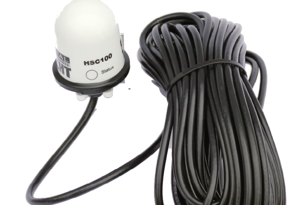
The devices from Furuno and Digital Yacht have buttons and displays to indicate progress and success or failure. Calibration can therefore be carried out completely independently of other devices. All competitors rely primarily on an instrument display or a plotter from their own company in order to carry out operation and display from there. For customers who do not have this, an emergency solution is provided: driving the full circles directly after switching on the compass power supply. The display is then shown at Garmin's 9-axis sensor and Raymarine via a light on the compass, on all Garmin devices and on Maretron via special course outputs. Raymarine and Navico can also carry out the calibration fully automatically if suitable course changes happen to have been made.
High-quality sensors and clean calculations are the ingredients for a good compass
But how can the compass know the correct north direction for this calibration process if it does not even know what errors its measurements show? It doesn't have to: a pinch of intelligent data processing together with the gyro is enough. The trick: the deviation causes the rotation rate determined by the magnetic field sensor to deviate from that of the gyro. Sometimes upwards, sometimes downwards during a full circle. The values for the deviation table can be calculated from these deviations.
One special feature concerns Raymarine: the AR200 expects a speed of between three and 15 knots for calibration according to the built-in GPS. Of course, this could not be achieved with the stationary test rig, which is why we cannot back up the good results on board with corresponding measurement data.
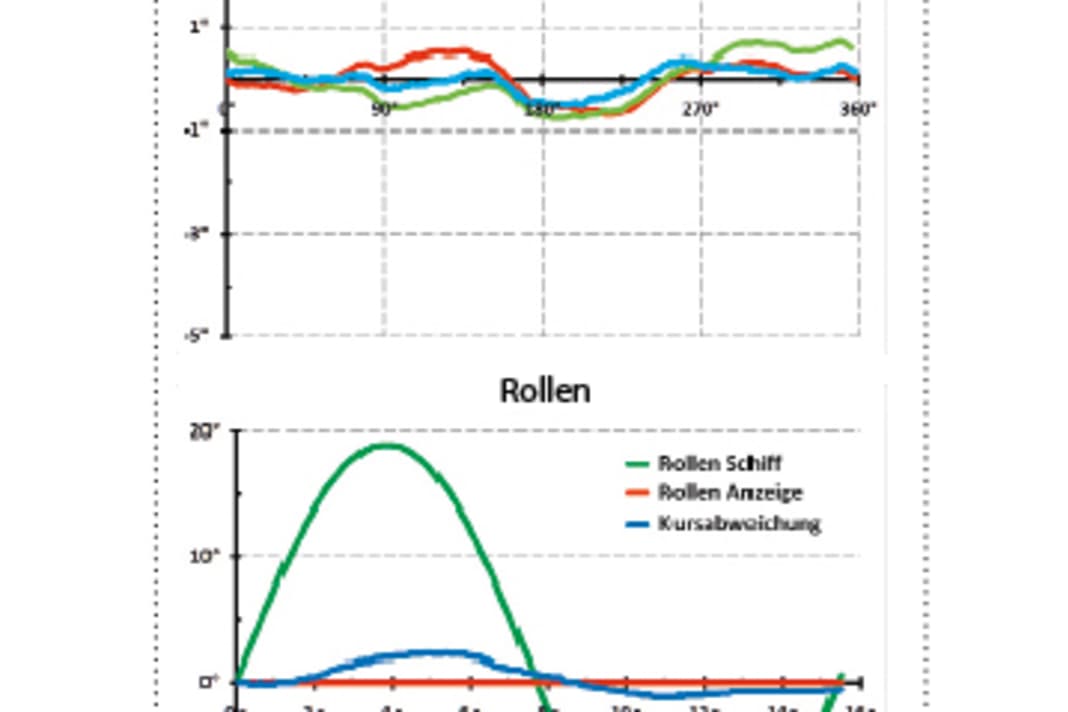
In the test, we set up the test stand so that a deviation of 15 degrees occurred before calibration. The result after calibration can be found for each compass in the diagram above. It shows the deviation over all courses. The blue line when the ship is horizontal, and also at ten degrees heel to port (red) and starboard (green). Deviations of up to one degree are good, up to three degrees are still acceptable. The larger your boat, the less important the red and green lines are: on a small fishing boat, two weighted anglers on the same side are required for a heel of ten degrees.
Mechanical Advance
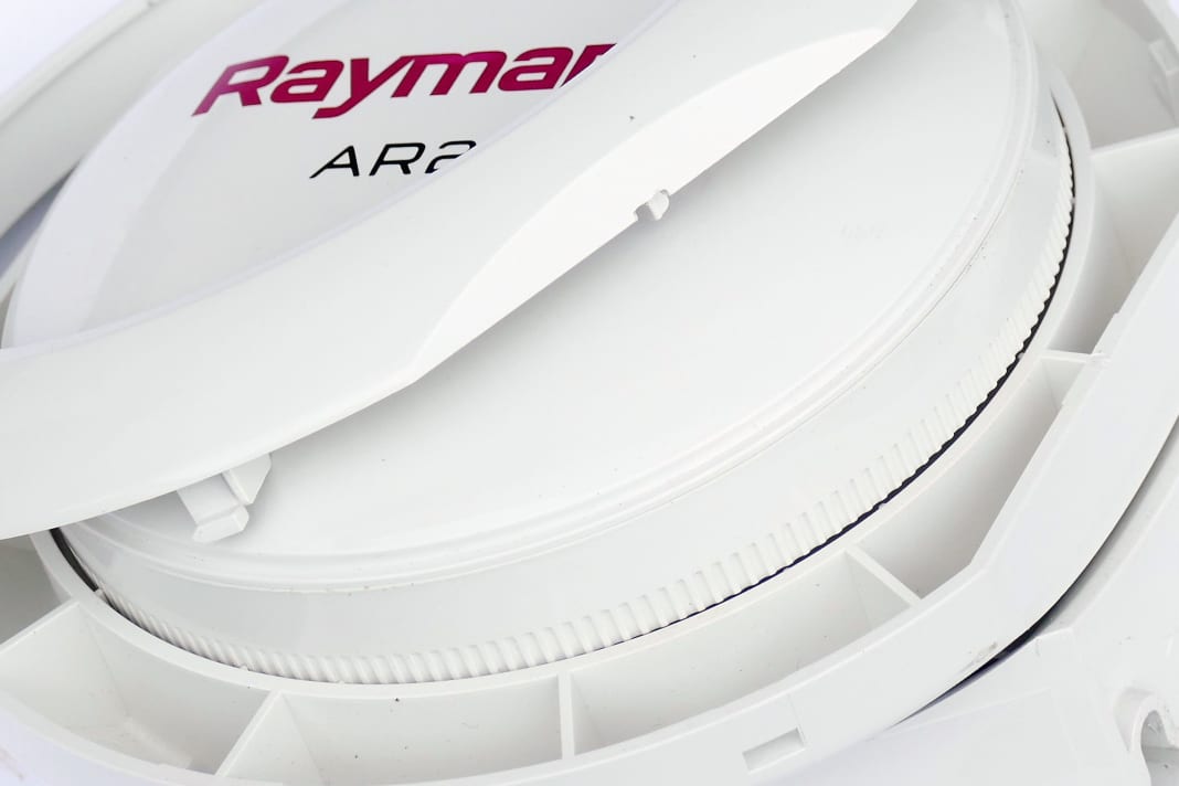
Less electronic correction means fewer rounding errors. The universal solution from Raymarine:


The second diagram shows the behaviour when rolling in rough seas. In the test, the test platform rolls extremely, within 16 seconds by 18 degrees to port and starboard, without changing course. The blue line is the deviation from the displayed course; it should be as close as possible to the zero degree line. The green line shows the actual inclination of the platform, the red line the heeling measurement result of the compass. The two should be as close to each other as possible. HSC100 , PG700 and SteadyCast do not measure the heel.
The last diagram is dedicated to manoeuvring; a tight S-curve is taken to determine the reaction time. The simulated boat turns 160 degrees to starboard and back again within eight seconds. If you want to try this out in practice, remove everything movable from the boat beforehand. The red line is the displayed course; it should be as close as possible to the green line (actual course). Blue is the rate of turn measured by the compass, grey is its actual value. HSC100, PG700 and SteadyCast do not measure the rate of turn.
In Precision 9, the course calculation overturns during this manoeuvre, generates an offset of 180 degrees and returns to the correct value within one minute. The effect only occurred in S-curves with rotation rates of over 50 degrees per second and is therefore insignificant in practice. If you make a hook like this, you are not steering it by instruments and have no view of the radar.


If a compass shows an accuracy of 0.1 degrees, then that is a great value and at least five times better than you need for most applications. Six devices boast the maximum resolution of 0.006 degrees possible with NMEA2000. Of course, this is of little use if the value swings back and forth by 0.5 degrees when the compass is screwed to the shore (this is called noise). Furuno fidgets the least at 0.05 degrees. Although Maretron keeps completely still at rest, it only displays with a coarser resolution of 0.1 degrees.
You can do a lot yourself to achieve a good result by mounting them exactly parallel to the centre line. The alignment can be corrected electronically on all models. However, the sensors for heeling and trim are not rotated at the same time: the resulting mutual influence must be elaborately calculated in the compass. The associated rounding errors can be easily avoided with a few washers (made of stainless steel, not galvanised).
Which one to choose? All candidates fulfil the usual requirements for radar overlay. Some applications such as augmented reality and all autopilots specify a specific compass.
The best course reference, even in rough seas Furuno's PG-700 . You get the most functions for your money with Navico's GS25, as long as your boat doesn't behave too nervously.
